Question
In: Physics
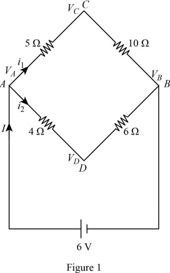
What is the current through the battery in the circuit shown below?
What is the current through the battery in the circuit shown below? What is the equivalent resistance between A and B for the network of resistors?
Solutions
Expert Solution
Concepts and reason
The concepts used to solve this problem are Ohm's law, the nodal analysis method, and Kirchhoff's junction rule. Use the concepts of junction rule and nodal analysis method in the given circuit to calculate the voltage at the nodes and as follow to calculate the total current flows in the circuit.
Then, use the voltage and obtained current flow to determine the equivalent resistance between \(A\) and \(B\) for the network of resistors.
Fundamentals
"The method of determining the voltage or potential difference between the nodes in an electrical circuit in terms of branch current is defined as nodal analysis" Kirchhoff's junction rule states that "The sum of electrical currents entering a junction is equal to the sum of currents leaving a junction in an electrical circuit". The expression for the junction rule is as follows:
\(\sum_{k=1}^{n} I_{\mathrm{k}}=0\)
Here, the current is \(I\) and the total number of the current measured is \(n\). Ohm's law states that "the voltage across a circuit is equal to the product of current and the resistance of the circuit". The expression for Ohm's law is as follows, \(V=I R\)
Here, the voltage is \(V\), the current is \(I\), and the resistance is \(R\).
The circuit diagram is redrawn as follows:

Here, the voltage across the junction \(A, B, C,\) and \(D\) are \(V_{A}, V_{B}, V_{C},\) and \(V_{D},\) total current is \(I,\) current flows
through the junction \(A C\) is \(i_{1}\), and current flows through the junction \(A D\) is \(i_{2}\).
Apply the nodal analysis law to node \(V_{C}\) as follows:
\(\frac{V_{C}-6}{5 \Omega}+\frac{V_{C}-V_{D}}{5 \Omega}+\frac{V_{C}}{10 \Omega}=0\)
\(\left(\frac{1}{5}+\frac{1}{5}+\frac{1}{10}\right) V_{C}-\frac{1}{5} V_{D}=\frac{6}{5}\)
$$ 0.5 V_{C}-0.2 V_{D}=1.2 \ldots \ldots(1) $$
Apply the nodal analysis law to node \(V_{D}\) as follows:
\(\frac{V_{D}-6}{4 \Omega}+\frac{V_{D}-V_{C}}{5 \Omega}+\frac{V_{C}}{6 \Omega}=0\)
\(\left(\frac{1}{4}+\frac{1}{5}+\frac{1}{6}\right) V_{D}-\frac{1}{5} V_{C}=\frac{6}{4}\)
$$ \begin{aligned} 0.62 V_{D}-0.2 V_{C} &=1.5 \\ V_{C} &=\frac{0.62 V_{D}-1.5}{0.2} \ldots \ldots \text { (2) } \end{aligned} $$
Substitute Equation (2) in (1). \(0.5\left(\frac{0.62 V_{D}-1.5}{0.2}\right)-0.2 V_{D}=1.2\)
$$ \begin{aligned} 1.55 V_{D}-0.2 V_{D}-3.75 &=1.2 \\ V_{D} &=\frac{4.95}{1.35} \\ &=3.667 \mathrm{~V} \end{aligned} $$
Substitute \(3.667 \mathrm{~V}\) for \(V_{D}\) in equation (1)
\(0.5 V_{C}-0.2(3.667 \mathrm{~V})=1.2\)
$$ \begin{aligned} V_{C} &=\frac{1.9334}{0.5} \\ &=3.867 \mathrm{~V} \end{aligned} $$
The expression to calculate the total current flow in the circuit is follow as:
\(I=i_{1}+i_{2}\)
Substitute \(\left(V_{A}-V_{C}\right) / 5\) for \(i_{1}\) and \(\left(V_{A}-V_{D}\right) / 4\) for \(i_{2}\).
\(I=\frac{V_{A}-V_{C}}{5}+\frac{V_{A}-V_{D}}{4}\)
Substitute \(6 \mathrm{~V}\) for \(V_{A}, 3.867 \mathrm{~V}\) for \(V_{C},\) and \(3.667 \mathrm{~V}\) for \(V_{D}\)
\(\begin{aligned} I &=\frac{6 \mathrm{~V}-3.867 \mathrm{~V}}{5}+\frac{6 \mathrm{~V}-3.667 \mathrm{~V}}{4} \\ &=\frac{2.133}{5}+\frac{2.333}{4} \\ &=1.01 \mathrm{~A} \end{aligned}\)
The expression for Ohm's law is as follows,
\(V=I R\)
The expression to calculate the equivalent resistance between \(A\) and \(B\) for the network of resistors is as follows:
\(V=I R_{e q}\)
Rearrange the expression to get \(R_{e q}\) \(R_{e q}=\frac{V}{I}\)
Substitute \(6 \mathrm{~V}\) for \(V\) and \(1.01 \mathrm{~A}\) for \(I\)
\(\begin{aligned} R_{e q} &=\frac{6 \mathrm{~V}}{1.01 \mathrm{~A}} \\ &=5.941 \Omega \\ &=6 \Omega \end{aligned}\)
The equivalent resistance between \(A\) and \(B\) for the network of resistors is \(6 \Omega\).
Related Solutions
For the circuit shown in the figure find the current through each resistor. For the circuit...
I have a circuit with a known battery voltage and a known primary current through the...
For the circuit shown in the figure, find the current through and the potential difference across...
For the circuit shown in the figure, find the current through resistor R3 =6.0 Ω
An RC circuit, hooked up to a battery as shown in the figure,starts with an...
Find the current through each of the three resistors of the circuit shown in the figure (Figure 1).
For the circuit shown in the figure, find the current through and the potential difference across each resistor.
Part A For the circuit shown in the figure(Figure 1) find the current through each resistor.
A battery that has a voltage of 20V is attached to a circuit. A current of...
Consider the circuit shown in the figure below. (Let R = 26.0 ohm.) Find the current...
- Kp has the value 1.00x10^-5 for the equilibrium CO2(g) + H2(g) <--> CO(g) + H2O(g) at...
- Write a MARIE program that asks the user for a beginning and an ending address of...
- Calculate the energy gap in J, kJ/mol, eV, and wavenumber (cm-1) between the level n =...
- 2. a. Choose all of the following that apply to DynamoDB: (a) DynamoDB is part of...
- I asked this question before, but I'm wondering if there are any other ways to do...
- Can you please Describe your actions as the Manager, and how you would manage the project...
- Suppose we have a collection of n different subsets of the set { 1, 2, ...,...
 Dr. OWL answered 5 years ago