Question
In: Physics
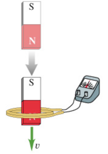
When a magnet is plunged into a coil at speed v, as shown in the figure, a voltage is induced in the coil and a current flows in the circuit.(Figure 1)
When a magnet is plunged into a coil at speed v, as shown in the figure, a voltage is induced in the coil and a current flows in the circuit. (Figure 1)
Part A
If the speed of the magnet is doubled, the induced voltage is ________.
- a.) twice as great
- b.) four times as great
- c.) half as great
- d.) unchanged
Solutions
Expert Solution
Concepts and reason
The concepts used to solve this problem are electromagnetic induction by a moving magnet and Faraday's law. Use the factors that depend on the electromagnetic induction of a moving magnet to find the correct option.
Fundamentals
“Faraday's law of induction states that whenever relative motion exists between a coil and magnetic field, a voltage will induce in the circuit and this voltage is proportional to the rate of change of the flux." The quick change in the flux will induce more emf than a gradual change. The expression for the motional emf is as follows:
\(\varepsilon=B l v\)
Here, \(\varepsilon\) is the motional emf, \(B\) is the magnetic field, \(l\) is the length of the conductor, and \(v\) is the velocity at which the magnetic field changes.
(A) The incorrect options are given below:
b) Four times as great
c) Half as great
d) Unchanged The expression for the motional emf is as follows:
\(\varepsilon=B l v\)
The induced voltage by the moving magnet is directly proportional to the speed of the magnet. Therefore, an increase in the speed of the magnet will increase the induced voltage.
The magnitude of the electromagnetic induction is equal to the product of flux density, length of the conductor, and the velocity of motion.
The correct option is given below:
b) Twice as great The expression for the motional emf is as follows:
\(\varepsilon=B l v\)
The magnitude of the induced voltage is proportional to the speed of the motion. Therefore, as the speed of the magnet is doubled, the induced voltage will be doubled. This is because the current will have to be twice as fast to keep up. Ohm's law:
\(V=I R\)
Here, \(\mathrm{V}\) is the potential difference, \(\mathrm{I}\) is the current, and \(\mathrm{R}\) is the resistance. If the resistance is constant, then the voltage must also be doubled.
Part A The induced voltage is twice, as the speed of the magnet is doubled.
An increase in the speed of the magnet will increase the induced voltage. Therefore, when the speed of the magnet is doubled, the induced voltage will also get doubled.
 Dr. OWL answered 5 years ago
Related Solutions
When a magnet is plunged into a coil at speed v, as shown in the figure, a voltage is induced in the coil and a current flows in the circuit.(Figure 1)
1- A magnet created when there is a current through a coil of wire is considered...
Consider the circuit shown in (Figure 1) . Suppose that E = 15 V
Consider the circuit shown in (Figure 1). Suppose that E = 7.0 V.
The loop in the figure has an induced current as shown. The loophas a resistance...
Consider the circuit shown in (Figure 1) . Suppose that E = 15 V . include...
Find the current through each of the three resistors of the circuit shown in the figure (Figure 1).
Part A For the circuit shown in the figure(Figure 1) find the current through each resistor.
For the circuit shown in the figure find the current through each resistor. For the circuit...
For the circuit shown in the figure, calculate the following. (Assume = 7.32 V and R =...
- Write a Bash script called move that could replace the UNIX command mv. 'move' tries to...
- Write program in C language using Pthreads API to simulate the real problem, the Sleeping Teaching...
- HF(g) + H2O(l) = H3O+(aq) + F-(aq) In the following equilibrium in a closed system, indicate...
- : Write a paragraph to reflect on what you have learned about Microsoft access in terms...
- Consider two markets: the market for cat food and the market for dog food. The initial...
- Why is business ethics unavoidable?
- mr. smith completed 9 years of fixed monthly payments of 3,333.28 on a 30 year loan...