Question
In: Physics
Consider the circuit shown in (Figure 1) . Suppose that E = 15 V
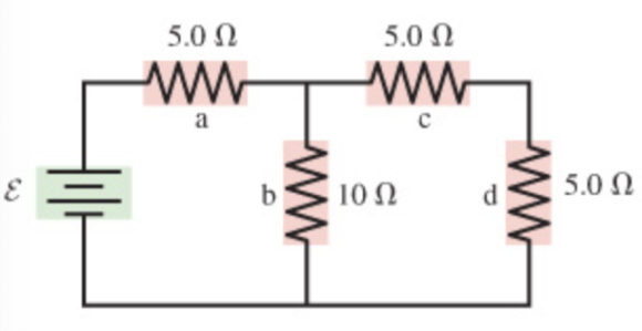
Consider the circuit shown in (Figure 1). Suppose that E = 15 V . include units with answers.
Part A: Find the current through the resistor a.
Part B: Find the potential difference across the resistor a. answer: 7.5 V
Part C: Find the current through the resistor b.
Part D: Find the potential difference across the resistor b.
Part E: Find the current through the resistor c.
Part F: Find the potential difference across the resistor c.
Part G: Find the current through the resistor d.
Part H: Find the potential difference across the resistor d.
Solutions
Expert Solution
Solution The resistances c and d are in series
$$ \begin{aligned} R_{x} &=R_{e}+R_{d} \\ &=5 \Omega+5 \Omega \\ &=10 \Omega \end{aligned} $$
Thus, total resistance in series is \(10 \Omega\)
The following diagram represents the simplified circuit diagram

Resistance \(b\) and \(R_{x}\) in parallel \(\frac{1}{R_{p}}=\frac{1}{R_{s}}+\frac{1}{R_{s}}\)
\(=\frac{1}{10 \Omega}+\frac{1}{10 \Omega}\)
\(=\frac{1}{5}\)
\(R_{p}=5 \Omega\)
Thus, total resistance in parallel is \(5 \Omega\)
$$ \begin{array}{l} \text { The following diagram represents the simplified circuit diagram } \\ \qquad 15 \mathrm{v}=\mathrm{VM} \end{array} $$
Equivalent resistance in the circuit
$$ \begin{aligned} R_{e q_{0}} &=R_{a}+R_{p} \\ &=5 \Omega+5 \Omega \\ &=10 \Omega \end{aligned} $$
Therefore, Equivalent resistance in the circuit is \(10 \Omega\)
(a) Current through the resistance a is, By Ohm's law
\(\begin{aligned} I_{a} &=\frac{V}{R_{\mathrm{eq} u}} \\ &=\frac{15 \mathrm{~V}}{10} \\ &=1.5 \mathrm{~A} \end{aligned}\)
Therefore, current through resistance a is \(1.5 \mathrm{~A}\)
(b) Potential difference through resistance a
\(\begin{aligned} V_{a} &=I_{a} R_{a} \\ &=1.5 \mathrm{~V} \times 5 \Omega \\ &=7.5 \mathrm{~V} \end{aligned}\)
Therefore, potential difference across a is \(7.5 \mathrm{~V}\)
(c) Current through the resistance b By \(O h m^{\prime}\) s law
\(\begin{aligned} I_{b} &=R_{\text {equ }} \times \frac{I_{a}}{R_{s}+R_{x}} \\ &=10 \Omega \times \frac{1.5 \mathrm{~A}}{10 \Omega+10 \Omega} \\ &=0.75 \mathrm{~A} \end{aligned}\)
Therefore, current through resistance b is \(0.75 \mathrm{~A}\)
(d)
Potential difference through resistance b
$$ \begin{aligned} V_{b} &=I_{b} R_{b} \\ &=0.75 \mathrm{~A} \times 10 \Omega \\ &=7.5 \mathrm{~V} \end{aligned} $$
Therefore, potential difference across b is \(\overline{7.5 \mathrm{~V}}\)
(e)
Current through the resistance By \(\mathrm{Ohm}^{\prime}\) s law
\(I_{e}=I_{a}-I_{b}\)
$$ \begin{array}{l} =1.5-0.75 \\ =0.75 \mathrm{~A} \end{array} $$
Therefore, current through resistance c is \(0.75 \mathrm{~A}\)
(f) Potential difference through resistance \(V_{e}=I_{e} R_{e}\)
$$ \begin{array}{l} =0.75 \mathrm{~A} \times 5 \Omega \\ =3.75 \mathrm{~V} \end{array} $$
Therefore, potential difference across c is \(3.75 \mathrm{~V}\)
(f) Potential difference through resistance \(V_{e}=I_{e} R_{e}\)
$$ \begin{array}{l} =0.75 \mathrm{~A} \times 5 \Omega \\ =3.75 \mathrm{~V} \end{array} $$
Therefore, potential difference across c is \(3.75 \mathrm{~V}\)
(g) Current through the resistance d By \(O h m^{\prime}\) s law
\(\begin{aligned} I_{d} &=I_{a}-I_{b} \\ &=1.5-0.75 \\ &=0.75 \mathrm{~A} \end{aligned}\)
Therefore, current through resistance d is \(0.75 \mathrm{~A}\)
(h) Potential difference through resistance d
$$ \begin{aligned} V_{d} &=I_{d} R_{d} \\ &=0.75 \mathrm{~A} \times 5 \Omega \\ &=3.75 \mathrm{~V} \end{aligned} $$
Therefore, potential difference across d is \(3.75 \mathrm{~V}\)
 Dr. OWL answered 5 years ago
Related Solutions
Consider the circuit shown in (Figure 1) . Suppose that E = 15 V . include...
Consider the circuit shown in (Figure 1). Suppose that E = 7.0 V.
Consider the circuit shown inthe figure. Suppose the four resistors in this circuit have the...
Consider an L-R circuit as shown in the figure. (Figure 1) The battery provides 12.0V of...
Consider the circuit in (Figure 1). Suppose that vs = 10V
For the circuit shown in the figure, calculate the following. (Assume = 7.32 V and R =...
Consider the circuit shown in the following figure. The battery has emf 50.0 V and negligible internal resistance.
What is the equivalent resistance for the circuit shown in the figure? (Figure 1) For the...
When a magnet is plunged into a coil at speed v, as shown in the figure, a voltage is induced in the coil and a current flows in the circuit.(Figure 1)
When a magnet is plunged into a coil at speed v, as shown in the figure, a voltage is induced in the coil and a current flows in the circuit.(Figure 1)
- Problem 18-12 Various shareholders' equity topics; comprehensive [LO18-1, 18-4, 18-5, 18-6, 18-7, 18-8] Part A In...
- Hello There, This is discussion Question For Advanced Database Systems Question: (a) Please define what a...
- Physicians at a clinic gave what they thought were drugs to 860860 patients. Although the doctors...
- On January 1, 2018, bonds with a face value of $ 79,000 were sold. The bonds...
- How do I make this sort in true alphabetical order instead of ascii(ABCabc) order? I am...
- As a healthcare provider in physical therapy, athletic training, or as an exercise scientist and personal...
- in the market for makeup artists, what happens after the invention of high-definition tv allowing viewers...