Question
In: Physics
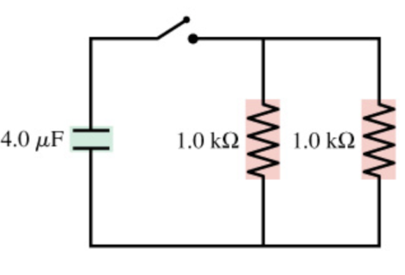
What is the time constant for the discharge of the capacitors in the figure (Figure 1) ?
What is the time constant for the discharge of the capacitors in the figure (Figure 1)?
Solutions
Expert Solution
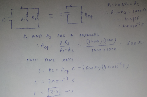
two 1 kilo ohms resistors are in parallel.
their equivalent resistance=(1000*1000)/(1000+1000)=500 ohms
time constant=R*C=500*4*10^(-6)=2 milli seconds
 Dr. OWL answered 5 years ago
Related Solutions
For the system of capacitors shown in the the figure below(Figure 1) , a potential difference...
For the system of capacitors shown in the figure
below(Figure
1), a potential difference of 25.0V is maintained across ab.Part (a): What is the equivalent capacitance of this system between a and b
in nF?Part (b): How much charge is stored by this system in nC?Part (c): How much charge does the 6.50 nF capacitor store in nC?Part (d): What is the potential difference across the 7.50 nF
capacitor in V?
Explain in detail about the discharge and precautions while working with the capacitors.
Explain in detail about the discharge and precautions
while working with the capacitors.
What total energy is stored in the capacitors in the figure below (C1 = 0.643
What total energy is stored in the capacitors in the figure
below
(C1 = 0.643
Four capacitors are arranged in the circuit shown in the figure
Four capacitors are arranged in the circuit shown in the figure. The capacitors have the values C1 = 23.5 μF, C2 = 45.5 μF, C3 = 50.5 μF, and C4 = 40.5 μF, and the power supply is at voltage V = 27.5 V. What is the equivalent capacitance of the circuit? equivalent capacitance: _______ μF What is the charge on capacitor C2? charge on C2:_______ CWhat is the potential difference across capacitor C3? potential difference across C3: _______ VWhat is the potential energy stored...
Consider the system of capacitors shown in the figure below
Consider the system of capacitors shown in the figure below (C1 = 4.00 μF,C2 = 2.00 μF). (a) Find the equivalent capacitance of the system. (b) Find the charge on each capacitor. (c) Find the potential difference across each capacitor (d) Find the total energy stored by the group.
Consider the system of capacitors shown in the figure below (C1 = 7.00
Consider the system of capacitors shown in the figure below
(C1 = 7.00
Two discharge wells (1 and 2) penetrating an unconfined aquifer are pumped at constant rates of...
Two discharge wells (1
and 2) penetrating an unconfined aquifer are pumped at constant
rates of 3,000 and 500 m^3 per day , respectively. The steady-state
head (i.e., water table height) measured at an observation well is
40 meters . The observation well is 50 meters from well 1 and 64
meters from well 2. The water table height measured at a second
observation well is 32.9 meters , which is located 20 meters from
well 1 and 23 meters...
What are real time devices important for patient monitoring after discharge
What are real time devices important for patient monitoring after
discharge
For the system of four capacitors shown in the figure below, find the following. (Use C1...
For the system of four capacitors shown in the figure below, find the following. (Use C1 = 1.00 μF, C2 = 4.00 μF, C3 = 2.00 μF. and C4 = 3.00 μF for the figure.) (a) the total energy stored in the system (b) the energy stored by each capacitor (c) Compare the sum of the answers in part (b) with your result to part (a) and explain your observation.
For the system of four capacitors shown in the figure below, find the following. (Use C1...
For the system of four capacitors shown in the figure below,
find the following. (Use C1 = 1.0
ADVERTISEMENT
ADVERTISEMENT
Latest Questions
- Consider two markets: the market for cat food and the market for dog food. The initial...
- Why is business ethics unavoidable?
- mr. smith completed 9 years of fixed monthly payments of 3,333.28 on a 30 year loan...
- during the experiment, a student did not follow the procedure exactly as directed how will eact...
- Assume all temperatures to be exact, and neglect significant figures for small changes in dimension. When...
- why is Argentina a developing country ?
- Calculate the enthalpy of the reaction 4B(s)+3O2(g)?2B2O3(s) given the following pertinent information: B2O3(s)+3H2O(g)?3O2(g)+B2H6(g), ?H?A=+2035 kJ 2B(s)+3H2(g)?B2H6(g),  
ADVERTISEMENT