Question
In: Physics
The conducting loop in the figure is moving into the region between the magnetic poles shown.
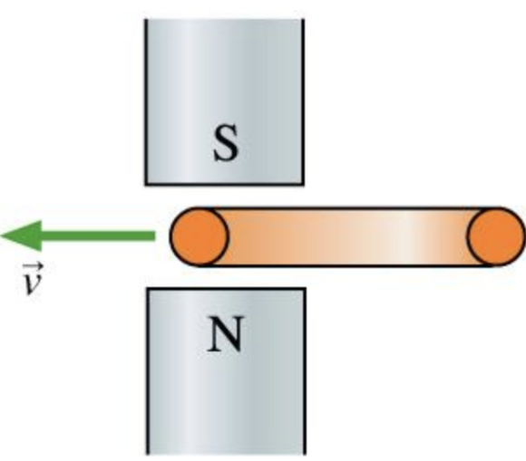
1. The conducting loop in the figure is moving into the region between the magnetic poles shown.
Is the induced current (viewed from above) clockwise or counterclockwise?
A. clockwise
B. counterclockwise
Solutions
Expert Solution
Concepts and reason
The concepts required to solve this problem are a force on a charge in a magnetic field and Lenz's law. Initially, find the direction of the force on charge carriers in the bar due to the magnetic field by using the right hand rule to find the direction of induced current. Finally, use Lenz's law to identify the correct statement for force.
Fundamentals
The right-hand thumb rule gives the direction of the force on a charged particle. If the fingers curl from the direction of velocity to the direction of the magnetic field, then the thumb points in the direction of the force exerted on the magnetic field. Lenz's law states that the emf induced in a conducting material by changing magnetic flux will create a magnetic field exactly opposite to the change in the applied magnetic flux.
(1) The magnetic field points from the North to south pole that is in the upward direction, and the bar is moving to the left. The fingers curl from the left direction to upwards—the thumb points into the plane of the page. So, the direction of force is into the plane. Thus, the induced current is clockwise as viewed from above.
Part 1 The induced current in the circuit is in a clockwise direction.
Refer to the figure; the magnetic field is upwards from the north pole to south pole, and velocity is towards left. Right hand rule gives the direction of force on the charge carriers in the bar. The bar is moving to the left and magnetic field is upwards. The force is into the plane, so the induced current is in a clockwise direction as viewed from above.
(2) The force is required to keep the rod moving, as from Lenz's law, the current is induced to oppose the change in magnetic flux. There is no attractive force from the magnet. The induced current in the rod results in a repulsive force in the magnetic field. Thus, you need to push the loop in against a repulsive force.
Part 2 You need to push the loop in against a repulsive force.
The induced current is generated in a direction to avoid the motion of the rod. So, there will be a repulsive force that opposes this motion.
 Dr. OWL answered 5 years ago
Related Solutions
1. The conducting loop in the figure is moving into the region between the magnetic poles...
A circular conducting loop of radius 25.0 cm is located in a region of homogeneous magnetic...
What is the magnetic field at the center of the loop in the figure? (figure 1)
State what is common between the geographic and magnetic poles of the earth
The magnetic field B_vec in a certain region is 0.128-axis in the Figure
The loop in the figure below is being pushed into the 0.20 T magnetic field at...
A long rectangular conducting loop of width 30 cm is partially in a region of a...
In the figure, a conducting rod of length L = 29.0 cm moves in a magnetic...
A conducting sphere is placed within a conducting spherical shell as shown in the figure below....
You are designing magnetic motors. A colleague1 insists that like magnetic poles attract— north poles attract...
- If banks must hold $4 in reserves for each $10 in deposits, and the public decides...
- A 244 g mass is hung on a spring. As a result the spring stretches 20.5...
- I'm trying to Generate number every 3 seconds and update the currenet number.I'm able to generate...
- a sulfide of iron, containing 36.5% S by mass, is heated in O2(g), and the products...
- Python previous function: wrtie a function that takes one argument. The function returns True if the...
- A professional couple wishes to purchase a new home costing $750,000, make a 20 percent down...
- Padre holds 100 percent of the outstanding shares of Sonora. On January 1, 2016, Padre transferred...