Question
In: Physics
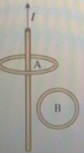
The current in the wire shown in (Figure 1) is increasing
The current in the wire shown in (Figure 1) is increasing.
Part A
What is the direction of the induced current in loop A?
- clockwise
- counterclockwise
- No current is induced in this loop.
Part B
- What is the direction of the induced current in loop B? clockwise
- counterclockwise
- No current is induced in this loop.
Solutions
Expert Solution
Part A.
Given that the current in the straight wire is increasing in the upward direction. Since the magnetic field due to the straight wire is parallel to the plane containing loop A, the net flux through loop A is zero. So, even if the current in the straight wire is changing the flux remains zero. Then, there should not be any induced current in the loop (No current in the loop).
Part B
The direction of the magnetic field due to the straight wire is into the page (within the loop B). Thus, the induced current in the loop B should be such that it opposes the increase of flux corresponding to the increase in the magnetic field is into the page. This is possible when the current in the loop is counterclockwise. Hence, the answer is counterclockwise.
 Dr. OWL answered 5 years ago
Related Solutions
An aluminum wire consists of the three segments shown in the following figure. The current in...
A long, straight wire carries a current of 20.0 A, as shown in Figure 27-63. A...
The right half of the square loop of wire shown in (Figure 1) is in a...
A piece of insulated wire is shaped into a figure eight as shown in the figure...
A metal wire is resting on a U-shaped conducting rail, as shown in (Figure 1) ....
In the figure below, the current in the long, straight wire is
The right half of the square loop of wire shown in Figure P24.37
Find the current through each of the three resistors of the circuit shown in the figure (Figure 1).
Part A For the circuit shown in the figure(Figure 1) find the current through each resistor.
What is the direction of the induced current in the wire shown in the picture?
- Problem 18-12 Various shareholders' equity topics; comprehensive [LO18-1, 18-4, 18-5, 18-6, 18-7, 18-8] Part A In...
- Hello There, This is discussion Question For Advanced Database Systems Question: (a) Please define what a...
- Physicians at a clinic gave what they thought were drugs to 860860 patients. Although the doctors...
- On January 1, 2018, bonds with a face value of $ 79,000 were sold. The bonds...
- How do I make this sort in true alphabetical order instead of ascii(ABCabc) order? I am...
- As a healthcare provider in physical therapy, athletic training, or as an exercise scientist and personal...
- in the market for makeup artists, what happens after the invention of high-definition tv allowing viewers...