Question
In: Computer Science
USE LOGISM Build a synchronous circuit using T flip-flops to detect (and hence signal with an...
USE LOGISM
Build a synchronous circuit using T flip-flops to detect (and hence signal with an output), the 3 bit sequence of 1 0 1. Use the example of the circuit that detects 3 consecutive 1's from Module 5, Topic 1 (pp. 11-16). Show your State Diagram, State Table, K-Maps, and properly formatted circuit diagram.
Solutions
Expert Solution
Solution:
State Diagram:

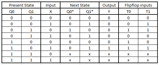
State Table:
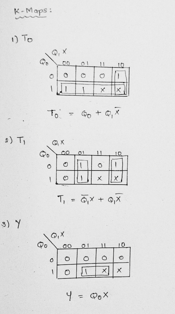
K-maps:
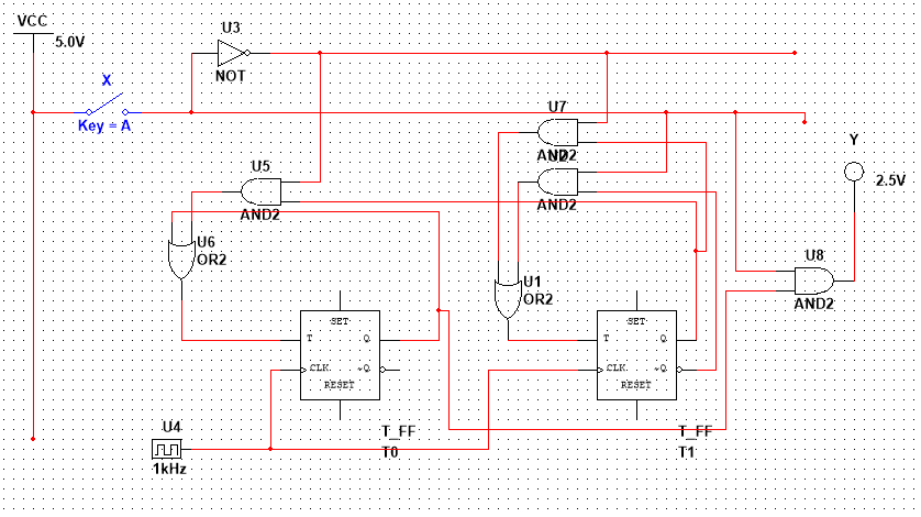
Circuit Diagram using multisim:
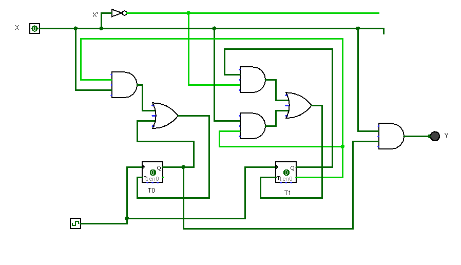
Circuit Diagram using Logisim:
Any queries comment, please
If you like my answer please upvote my answer
Thank you :)
 venereology answered 2 months ago
Related Solutions
Design sequential circuit for detect 11011 sequence using D flip flops clearly indicating the procedure and...
Design sequential circuit for detect 11011 sequence using D flip
flops clearly indicating the procedure and relevant diagrams. Write
vrilog code for your circuit.
Step by step answers please.
Attach a screenshot of Multisim circuit. flip flops: D, T and JK, connect the circuit and...
Attach a screenshot of Multisim circuit. flip flops: D, T and
JK, connect the circuit and verify the characteristic tables.
Design a synchronous counter, using T flip-flops, that has the following sequence: 0010, 0110, 1000, 1001,...
Design a synchronous counter, using T flip-flops, that has the
following sequence: 0010, 0110, 1000, 1001, 1100, 1101, and repeat.
From the undesired states the counter must always go to 0010 on the
next clock pulse.
Design a synchronous counter of four-bit using D flip‐flops and gates (AND, OR etc.) *use verilog...
Design a synchronous counter of four-bit using D flip‐flops and
gates (AND, OR etc.)
*use verilog language modules and test and explain briefly
Using Multisim, connect the circuit and verify the characteristic tables for the following flip flops: D,...
Using Multisim, connect the circuit and verify the
characteristic tables for the following flip flops: D, T and JK
Add 4 screen shots which verify the characteristic table
2 for D, T, and JK FF.
2 more for remaining input combinations of JK
detect 1010 using T flip-flop with allowing overlap
detect 1010 using T flip-flop with allowing overlap
Design a 5-bit binary counter using JK flip flops. Draw the flip-flop circuit diagram, the state...
Design a 5-bit binary counter using JK flip flops.
Draw the flip-flop circuit diagram, the state graph, the timing
diagram, the truth table (with clk pulse) and the state table (with
present and next states).
Describe the differences between SR latches, D latches, D flip flops, JK flip flops, and T...
Describe the differences between SR latches, D latches, D flip
flops, JK flip flops, and T flip flops.
Detect "010" using Moore state machine, overlapped, and minimized-bit state encoding. Use JK flip-flops. Shows your...
Detect "010" using Moore state machine, overlapped, and
minimized-bit state encoding. Use JK flip-flops. Shows your state
diagram, state table, encoded state table, logic equations, and
logic circuit.
Design a sequential circuit with 2 JK flip-flops A and B, and 2 inputs, E...
Design a sequential circuit with 2 JK flip-flops A and B, and 2 inputs, E and x. the design must adhere to the following requirements: If E = 0, the circuit remains in the same state regardless of the value of x. When E = 1 and x = 1, the circuit goes through the state transitions from 00 to 01 to 10 to 11 back to 00 and repeats. When E = 1 and x = 0, the circuit goes through the...
ADVERTISEMENT
ADVERTISEMENT
Latest Questions
- IT Project Management: Explain in detail and give 3 references: What are some ways to manage...
- “A working mother receives $300,000 salary, while spends $30,000 for hiring baby-sitter.” What's the impact on...
- In a women's 100-m race, accelerating uniformly, Laura takes 1.90 s and Healan 3.15 s to...
- The HUANG Company currently has one bond issue outstanding. This bond pays a coupon rate of...
- These two waves travel along the same string: y1 = (3.52 mm) sin(1.75?x - 470?t) y2...
- An analyte has been discovered ( so it's new) in the Tobago population. Define the term...
- A freestyle skier is training for the Olympics. In this sport the skier starts at the...
ADVERTISEMENT