Question
In: Computer Science
briefly describ major element of the structuar models in ood with UML
Solutions
Expert Solution
Answer:
Object-oriented design (OOD) is the process of using an object-oriented methodology to design a computing system or application. This technique enables the implementation of a software solution based on the concepts of objects.
OOD serves as part of the object-oriented programming (OOP) process or lifecycle.
In object-oriented system design and development, OOD helps in designing the system architecture or layout - usually after completion of an object-oriented analysis (OOA). The designed system is later created or programmed using object-oriented based techniques and/or an object-oriented programming language (OOPL).
The OOD process takes the conceptual systems model, use cases, system relational model, user interface (UI) and other analysis data as input from the OOA phase. This is used in OOD to identify, define and design systems classes and objects, as well as their relationship, interface and implementation.
Structural models:
Structural models of software display the organization of a system in terms of the components that make up that system and their relationships. Structural models may be static models, which show the structure of the system design or dynamic models, which show the organization of the system when it is executing. These are not the same things—the dynamic organization of a system as a set of interacting threads may be very different from a static model of the system components.
Important
A domain model is a representation of real-world conceptual classes, not of software components. It is not a set of diagrams describing software classes, or software objects with responsibilities. A domain model serves as a visual dictionary of abstractions.
UML uses class diagrams at all abstraction levels to describe the static structure of a system. Starting from domain classes and abstract concepts through design patterns till the constructs of programming language(s) used for the implementation, we use classes. However, you should not think that the same name means the same construct: a UML class and a Java class, for example, might be quite similar and very different, as well. This is because UML uses 4 interpretations when talking about classes:
Table: UML interpretations of classes
| Class as a concept | Classes can be used to document and define concepts. We use classes to describe (more) abstract concepts based on some existing concepts. |
| Class as a data type | Classes can be considered as data types. Object instances are considered to be the values of the data type so a class is defined by its internal structure (intension). |
| Class as a set of objects | Classes can be seen as a set of similar objects that belong to the same class (extension). |
| Class as implementation | In object-oriented programming languages classes play only the role of an implementation that is shared among the instances. |
Class diagrams appear in different contexts. It is very convenient to classify them based on the stages of the software engineering lifecycle where they are used.
Analysis-level classes are the elements of the problem domain. They help us to understand and document the problem space.
Design-level classes are about how to transform domain structures into technical structures so we work in the solution space instead of the problem space. Design-level classes combine domain motivations with technical aspects. Some of the classes are closer to the domain elements while others are closer to the elements of the solution.
Implementation-level classes show how a solution is given. These classes map directly to the corresponding construct of the implementation language (Java, C# or C++, etc.).
First we need to establish an analysis-level class diagram as this is waht is needed to describe the problem domain itself. To achieve this, an abstraction process is needed: we need to find out what elements (constructs) of the real world are important for our universe of discourse, how can the concepts of the problem domain be revealed.
We choose attributes that support the ideas of likeness we have in mind when abstracting the class. Relationships exist between the things of the domain that are abstracted to associations between classes. The result of this abstraction process is an analysis-leve class diagram that will serve as a good source for further refinements (to evolve it into design-level and probably implementation-level diagrams).
|
Seven Types of Structural Things |
|
| 1. Class - An object with defined attributes and operations. A class in UML is very much like a class in C++. |
|
| 2. Interface - A collection of functions that specify a service of a class or component, i.e. externally visible behavior of that class. |
|
| 3. Collaboration - A larger pattern of behaviors and actions. Example: All classes and behaviors that create the modeling of a moving tank in a simulation. |
|
| 4. Use Case - A sequence of actions that a system performs that yields an observable result. Used to structure behavior in a model. Is realized by a collaboration. |
|
| 5. Active Class - Like a class but its represents behavior that runs concurrent with other behaviors, i.e. threading. |
|
| 6. Component - A physical and replaceable part of a system that implements a number of interfaces. Example: a set of classes, interfaces, and collaborations. |
|
| 7. Node - A physical element existing at run time and represents a resource. |
|


Class Diagram with an Example:
Class diagram is a static diagram. It represents the static view of an application. Class diagram is not only used for visualizing, describing, and documenting different aspects of a system but also for constructing executable code of the software application.
Class diagram describes the attributes and operations of a class and also the constraints imposed on the system. The class diagrams are widely used in the modeling of objectoriented systems because they are the only UML diagrams, which can be mapped directly with object-oriented languages.
Class diagram shows a collection of classes, interfaces, associations, collaborations, and constraints. It is also known as a structural diagram.
Purpose of Class Diagrams
The purpose of class diagram is to model the static view of an application. Class diagrams are the only diagrams which can be directly mapped with object-oriented languages and thus widely used at the time of construction.
UML diagrams like activity diagram, sequence diagram can only give the sequence flow of the application, however class diagram is a bit different. It is the most popular UML diagram in the coder community.
The purpose of the class diagram can be summarized as −
-
Analysis and design of the static view of an application.
-
Describe responsibilities of a system.
-
Base for component and deployment diagrams.
-
Forward and reverse engineering.
How to Draw a Class Diagram?
Class diagrams are the most popular UML diagrams used for construction of software applications. It is very important to learn the drawing procedure of class diagram.
Class diagrams have a lot of properties to consider while drawing but here the diagram will be considered from a top level view.
Class diagram is basically a graphical representation of the static view of the system and represents different aspects of the application. A collection of class diagrams represent the whole system.
The following points should be remembered while drawing a class diagram −
- The name of the class diagram should be meaningful to describe the aspect of the system.
- Each element and their relationships should be identified in advance.
- Responsibility (attributes and methods) of each class should be clearly identified
- For each class, minimum number of properties should be specified, as unnecessary properties will make the diagram complicated.
- Use notes whenever required to describe some aspect of the diagram. At the end of the drawing it should be understandable to the developer/coder.
- Finally, before making the final version, the diagram should be drawn on plain paper and reworked as many times as possible to make it correct.
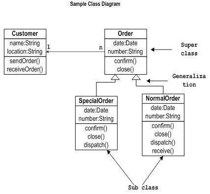
- The following diagram is an example of an Order System of an application. It describes a particular aspect of the entire application.
- First of all, Order and Customer are identified as the two elements of the system. They have a one-to-many relationship because a customer can have multiple orders.
- Order class is an abstract class and it has two concrete classes (inheritance relationship) SpecialOrder and NormalOrder.
- The two inherited classes have all the properties as the Order class. In addition, they have additional functions like dispatch () and receive ().
- Describing the static view of the system.
- Showing the collaboration among the elements of the static view.
- Describing the functionalities performed by the system.
- Construction of software applications using object oriented languages.
The following class diagram has been drawn considering all the points mentioned above.
 venereology answered 1 year ago
Related Solutions
briefly describe major element of the structural model in ood with Uml
Describe what business rules are and how they are incorporated into BPMN Activity models and UML...
Describe what business rules are and how they are incorporated into BPMN Activity models and UML...
Who were the three major contributors to the UML notation, and what are their contributions?
Briefly describe the three Oligopoly models
Briefly explain Greece Crisis with ADAS / ISLM models.
Briefly explain the need for alternative models of ownership in transportation. What models seem more appropriate...
There are many theoretical models of professional reflection. Briefly describe two models. You may use graphics...
Briefly define each of the three elements of the fraud triangle and the fourth element of...
China is a major element of strategic planning for managers and investors. 1. What are the...
- describe why independent oversight is important to taxpayers.
- Graph a Monopoly. Compare the price, quantity, and ATC of a monopoly with a perfectly competitive...
- Problem 18-12 Various shareholders' equity topics; comprehensive [LO18-1, 18-4, 18-5, 18-6, 18-7, 18-8] Part A In...
- Hello There, This is discussion Question For Advanced Database Systems Question: (a) Please define what a...
- Physicians at a clinic gave what they thought were drugs to 860860 patients. Although the doctors...
- On January 1, 2018, bonds with a face value of $ 79,000 were sold. The bonds...
- How do I make this sort in true alphabetical order instead of ascii(ABCabc) order? I am...