Question
In: Electrical Engineering
1. May you expalin why induction motors are necessary and the difference if induction motors with...
Solutions
Expert Solution
1. An induction motor (also known as an asynchronous motor) is a commonly used AC electric motor. In an induction motor, the electric current in the rotor needed to produce torque is obtained via electromagnetic induction from the rotating magnetic field of the stator winding. The rotor of an induction motor can be a squirrel cage rotor or wound type rotor.
Induction motors are referred to as ‘asynchronous motors’ because they operate at a speed less than their synchronous speed.
Them most important advantage of an induction motor is that its construction is quite simple in nature. The construction of the Stator is similar in both Synchronous motors as well as induction motors. However, a slip ring is required to feed DC Supply to the Rotor in the case of a Synchronous Generator. These Slip rings are not required in a Squirrel cage induction motorbecause the windings are permanently short circuited. When compared with a DC Motor, the induction motor does not have Brushes and hence, maintenance required is quite low. This leads to a simple construction.
The working of the motor is independent of the environmental condition. This is because the induction motor is Robust and mechanically strong.
A Squirrel cage induction motor does not contain Brushes, Slip rings and Commutators. Due to this reason, the cost of the motor is quite low. However, Slip Rings are used in Wound type induction motor to add external resistanceto the rotor winding.
Due to the absence of Brushes, there are no sparks in the motor. It can also be operated in hazardous conditions.
Unlike synchronous motors, a 3 phase induction motor has a high starting torque, good speed regulation and reasonable overload capacity.
An induction motor is a highly efficient machine with full load efficiency varying from 85 to 97 percent.
2. Air Circuit Breakers
This type of circuit breakers, is those kind of circuit breaker which operates in air at atmospheric pressure. After development of oil circuit breaker, the medium voltage air circuit breaker(ACB) is replaced completely by oil circuit breaker in different countries. But in countries like France and Italy, ACBs are still preferable choice up to voltage 15 KV. It is also good choice to avoid the risk of oil fire, in case of oil circuit breaker. In America ACBs were exclusively used for the system up to 15 KV until the development of new vacuum and SF6 circuit breakers.
Working Principle of Air Circuit Breaker
The working principle of this breaker is rather different from those in any other types of circuit breakers. The main aim of all kind of circuit breaker is to prevent the reestablishment of arcing after current zero by creating a situation where in the contact gap will withstand the system recovery voltage. The air circuit breaker does the same but in different manner. For interrupting arc it creates an arc voltage in excess of the supply voltage. Arc voltage is defined as the minimum voltage required maintaining the arc. This circuit breaker increases the arc voltage by mainly three different ways,
It may increase the arc voltage by cooling the arc plasma. As the temperature of arc plasma is decreased, the mobility of the particle in arc plasma is reduced; hence more voltage gradient is required to maintain the arc.
It may increase the arc voltage by lengthening the arc path. As the length of arc path is increased, the resistance of the path is increased, and hence to maintain the same arc current more voltage is required to be applied across the arc path. That means arc voltage is increased.
Splitting up the arc into a number of series arcs also increases the arc voltage.
Operation of ACB
- The first objective is usually achieved by forcing the arc into contact with as large an area as possible of insulating material. Every air circuit breaker is fitted with a chamber surrounding the contact. This chamber is called ‘arc chute’. The arc is driven into it. If inside of the arc chute is suitably shaped, and if the arc can be made conform to the shape, the arc chute wall will help to achieve cooling. This type of arc chute should be made from some kind of refractory material. High temperature plastics reinforced with glass fiber and ceramics are preferable materials for making arc chute.
- The second objective that is lengthening the arc path, is achieved concurrently with fist objective. If the inner walls of the arc chute is shaped in such a way that the arc is not only forced into close proximity with it but also driven into a serpentine channel projected on the arc chute wall. The lengthening of the arc path increases the arc resistance.
- The third technique is achieved by using metal arc slitter inside the arc chute. The main arc chute is divided into numbers of small compartments by using metallic separation plates. These metallic separation plates are actually the arc splitters and each of the small compartments behaves as individual mini arc chute. In this system the initial arc is split into a number of series arcs, each of which will have its own mini arc chute. So each of the split arcs has its own cooling and lengthening effect due to its own mini arc chute and hence individual split arc voltage becomes high. These collectively, make the overall arc voltage, much higher than the system voltage.
This was working principle of air circuit breaker now we will
discuss in details the operation of ACB in practice.
The air circuit breaker, operated within the voltage level 1 KV,
does not require any arc control device. Mainly for heavy fault
current on low voltages (low voltage level above 1 KV) ABCs with
appropriate arc control device, are good choice. These breakers
normally have two pairs of contacts. The main pair of contacts
carries the current at normal load and these contacts are made of
copper. The additional pair is the arcing contact and is made of
carbon. When circuit breaker is being opened, the main contacts
open first and during opening of main contacts the arcing contacts
are still in touch with each other. As the current gets, a parallel
low resistive path through the arcing contact during opening of
main contacts, there will not be any arcing in the main contact.
The arcing is only initiated when finally the arcing contacts are
separated. The each of the arc contacts is fitted with an arc
runner which helps, the arc discharge to move upward due to both
thermal and electromagnetic effects as shown in the figure. As the
arc is driven upward it enters in the arc chute, consisting of
splitters. The arc in chute will become colder, lengthen and split
hence arc voltage becomes much larger than system voltage at the
time of operation of air circuit breaker, and therefore the arc is
quenched finally during the current zero.

Although these types of circuit breakers have become obsolete for
medium voltage application, but they are still preferable choice
for high current rating in low voltage application.
Advantages of Air Circuit Breaker
- The Operation of Air circuit Breaker is easy and simple.
- The whole construction is simple and inexpensive
- The arc quenching medium is easily available in atmosphere
- Simple maintenance requirements only monitoring the air pressure in the cabinet.
- Fire hazards will not happen in case of insulation damage of the cabinet as in the case of oil circuit breaker.
Disadvantages of Air Circuit Breaker
- The operating voltage is limited to <10 KV because of less dielectric strength compared to SF6 and air blast.
- The interrupting current capacity is limited to 10000 A.
3. Cycloconvertor
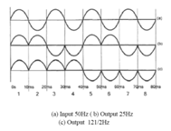
A cycloconverter is a device that converts AC, power at one frequency into AC power of an adjustable but lower frequency without any direct current, or DC, stage in between. It can likewise be acknowledged as a static recurrence charger and holds silicon-regulated rectifiers. Cyclo-converters are used in very large variable frequency drives with ratings from few megawatts up to many tens of megawatts.The principle of the cyclo-converter is described below by using single-phase to single-phase cyclo-converter.A single phase input cycloconverter is shown below (a) 50 Hz, (b) 25Hz, (c) 12.5 Hz single-phase input to single-phase output cycloconverter is shown below
Rectifier converts from Single-phase or three-phase AC to variable dc Voltage. Choppers converts from DC to variable dc voltage. Inverters convert from DC to variable magnitude variable frequency single-phase or three-phase AC. Cyclic converters convert from single-phase or three-phase AC to variable magnitude variable frequency single-phase or three-phase AC. A cycloconverter is having four thyristors divided into a positive and negative bank of two thyristors each.
Cycloconverter Basic Schematic:
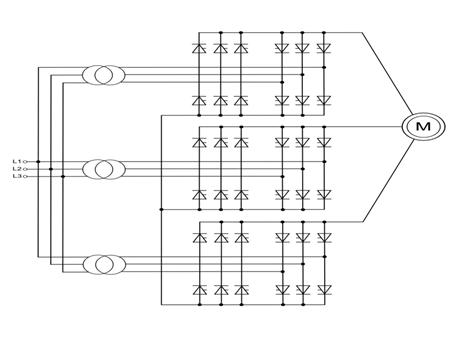
Cycloconverter
4. Thyristor
SCR or Thyristor is a four-layered, three-junction semiconductor switching device. It has three terminals anode, cathode, and gate. Thyristor is also a unidirectional device like a diode, which means it flows current only in one direction. It consists of three PN junction in series as it is of four layers. Gate terminal used to trigger the SCR by providing small voltage to this terminal, which we also called gate triggering method to turn ON the SCR.

Symbol

Schematic diagram
The main application of thyristors is to control high power
circuits.
• They find applications in power supplies for digital
circuits.
• AC & DC motor speed controllers consist of thyristors.
• A thyristor is also used in light dimmers.
Thermistor
A thermistor (or thermal resistor) is defined as a type of resistor whose electrical resistance varies with changes in temperature. Although all resistors’ resistance will fluctuate slightly with temperature, a thermistor is particularly sensitive to temperature changes.
Thermistors act as a passive componentin a circuit. They are an
accurate, cheap, and robust way to measure temperature. While they
do not work well in extremely hot or cold temperatures, they are
the sensor of choice for many different applications. They are
ideal when a precise temperature reading is required. The circuit
symbol for a thermistor is shown below:
Uses of Thermistors
Thermistors have a variety of applications. They are widely used as a way to measure temperature as a thermistor thermometer in many different liquid and ambient air environments. Some of the most common uses of thermistors include:
- Digital thermometers (thermostats)
- Automotive applications (to measure oil and coolant temperatures in cars & trucks)
- Household appliances (like microwaves, fridges, and ovens)
- Circuit protection (i.e. surge protection)
- Rechargeable batteries (ensure the correct battery temperature is maintained)
- To measure the thermal conductivity of electrical materials
- Temperature compensation (i.e. maintain resistance to compensate for effects caused by changes in temperature in another part of the circuit)
- Used in wheatstone bridge circuits
The working principle of a thermistor is that its resistance is dependent on its temperature. We can measure the resistance of a thermistor using an ohmmeter. If we know the exact relationship between how changes in the temperature will affect the resistance of the thermistor – then by measuring the thermistor’s resistance we can derive its temperature.
How much the resistance changes depends on the type of material used in the thermistor. The relationship between a thermistor’s temperature and resistance is non-linear. A typical thermistor graph is shown below:

If we had a thermistor with the above temperature graph, we could simply line up the resistance measured by the ohmmeter with the temperature indicated on the graph. By drawing a horizontal line across from the resistance on the y-axis, and drawing a vertical line down from where this horizontal line intersects with the graph, we can hence derive the temperature of the thermistor.
 Manojponduru answered 2 years ago
Related Solutions
Expalin the difference between variable and fixed costs
If you had to auction off a cow, which auction would you use and why? expalin...
Briefly explain the Big Push Theory. And why it may it be necessary.
What is similarity and difference between first principle induction and second principle induction ? When to...
What is the difference between induction and charging by conduction?
Explain why the induction cooker stays cold? And why save energy with an induction cooker?
What is similarity and difference between first principle induction mathematical and second principle induction mathematical ?...
1. why is assessing job performance necessary?
List the starting methods used in starting 3-phase induction motors and explain any two of these...
Q. Two 3-phase induction motors A, B are identical in all respects except that motor A...
- Graph a Monopoly. Compare the price, quantity, and ATC of a monopoly with a perfectly competitive...
- Problem 18-12 Various shareholders' equity topics; comprehensive [LO18-1, 18-4, 18-5, 18-6, 18-7, 18-8] Part A In...
- Hello There, This is discussion Question For Advanced Database Systems Question: (a) Please define what a...
- Physicians at a clinic gave what they thought were drugs to 860860 patients. Although the doctors...
- On January 1, 2018, bonds with a face value of $ 79,000 were sold. The bonds...
- How do I make this sort in true alphabetical order instead of ascii(ABCabc) order? I am...
- As a healthcare provider in physical therapy, athletic training, or as an exercise scientist and personal...