Question
In: Electrical Engineering
What is the cutoff frequency? What is the Butterworth response of a filter? What are the...
-
What is the cutoff frequency?
-
What is the Butterworth response of a filter?
-
What are the differences between first-order and second-order filters?
Solutions
Expert Solution
i) CUTOFF FREQUENCY
The cutoff frequency is given by the equation:
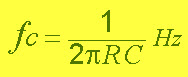
Cutoff Frequency
Cutoff frequency is the frequency at which magnitude if filter is is 3db lower than maximum magnitude.
thus, all high frequencies above the cut-off point band rolls down to zero at 20dB per decade or 6dB per octave in the stop band for first order filter.
ii) Frequency response of Butterworth filter
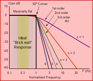
Butterworth Filter Ideal Frequency Response
The frequency response of the nth order Butterworth filter is given as
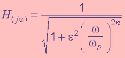
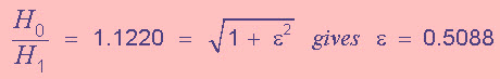
Where ‘n’ indicates the filter order, ‘ω’ = 2πƒ, Epsilon ε is maximum pass band gain, (Amax). If we define Amax at cut-off frequency -3dB corner point (ƒc), then ε will be equal to one and thus ε2 will also be equal to one. But, if we want to define Amax at another voltage gain value, consider 1dB, or 1.1220 (1dB = 20logAmax) then the value of ε can be found by:
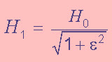
Where, H0 represents the maximum pass band gain and H1 represents the minimum pass band gain. Now, if we transpose the above equation, then we will get
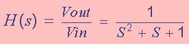
By using the standard voltage transfer function, we can define the frequency response of Butterworth filter as
![]()
Where, Vout indicates voltage of output signal, Vin indicates input voltage signal, j is square root of -1, and ‘ω’ = 2πƒ is the radian frequency. The above equation can be represented in S-domain as given below
iii) Difference between First order and second order filter
a.)
Order basically defines the rolloff rate how does it attenuate the signals a first order filter has -20db/decade roll off past of cutoff frequency.
Second order has -40 db/ decade.
b.)
Basically 2nd order is better in filtering than first order.
c.)
A first order filter would have one capacitor or one inductor, that affects the filters frequency response. A second order filter would have two capacitors or two inductors, or one capacitor and one inductor, that affects the filter's frequency response.
 Manojponduru answered 4 years ago
Related Solutions
a. Design a broadband Butterworth bandpass filter with a lower cutoff frequency of 500 Hz and...
Butterworth filter a)Design a 5th order low pass Butterworth low-pass filter with a cut-off frequency of...
Design an active high pass filter with a high frequency gain of 5 and a cutoff...
Design a bandstop filter with a cutoff frequency of -3dB at W1 = 100 rad/s and...
Design a 3-pole Butterworth low-pass filter with a DC gain of 5 and a -3db frequency...
Design and simulate a first order low pass filter so that it has a cutoff frequency...
Design and simulate a first order high pass filter so that it has a cutoff frequency...
Create a 2nd order Butterworth 150 Hz frequency low pass filter. Please provide transfer function and...
Design a first order, high pass active filter with a cutoff frequency of 20 krad/sec. Cascade...
What I am trying to do is to design a Butterworth Bandpass filter using Matlab, High...
- Question 3 (a) What do you understand by a time series forecasting approach? Describe each of...
- 1 Which of the following overflow values clips all content that extends beyond the containing element’s...
- What are the key environmental and biological controls over decomposition rate in ecosystems?
- describe why independent oversight is important to taxpayers.
- Graph a Monopoly. Compare the price, quantity, and ATC of a monopoly with a perfectly competitive...
- Problem 18-12 Various shareholders' equity topics; comprehensive [LO18-1, 18-4, 18-5, 18-6, 18-7, 18-8] Part A In...
- Hello There, This is discussion Question For Advanced Database Systems Question: (a) Please define what a...