Question
In: Physics
What is an electrical transformer? Discuss basic principles of operation and applications of electrical transformers
Discussion Question 1:
What is an electrical transformer? Discuss basic principles of operation and applications of electrical transformers. Can you relate electromagnetic induction to the operation a transformer?
Discussion Question 2:
Discuss similarities and differences between RL and RLC Circuits. How can one tell if an RLC circuit is underdamped or overdamped? What are some applications of RLC Circuits?
Solutions
Expert Solution
TRANSFORMER
A transformer is a static device which transfers electrical energy from one circuit to another through the process of electromagnetic induction. It is most commonly used to increase (‘step up’) or decrease (‘step down’) voltage levels between circuits
Theory of Operation
Transformers rely on Faraday's Law, which states that a time-varying magnetic field can induce a time-varying voltage in a loop of wire. In a transformer, this is accomplished by wrapping multiple turns of wire around some type of ferromagnetic material. Usually, there are two sets of windings: a primary and a secondary. The primary winding is attached to the generator; the secondary side is attached to the load. When a time-varying voltage is applied to the primary, a magnetic field is created inside the ferromagnetic core. The ferromagnetic material serves to concentrate the magnetic flux within the windings. The magnetic flux on the outside of the windings is reduced and the efficiency of the device is increased.
The time-varying magnetic field induces a voltage in the secondary winding.
The magnitude of the secondary voltage depends on the turns ratio of the primary and secondary windings. Suppose that the secondary winding of a transformer has 100 turns, while the primary winding has only 50 turns. The resulting secondary voltage will be twice that of the primary voltage. Likewise, if the primary has 100 turns, and the secondary has 50 turns, the secondary voltage would be half that of the primary.
At this point, it may seem that we're getting something for nothing, but this is not the case. Recall that energy can neither be created nor destroyed. We know that the electrical power flowing into the primary windings is the product of the current and voltage. Similarly, the power flowing out of the transformer must also be a product of its current and voltage. Neglecting losses in the transformer core, the power entering the transformer must also be the power leaving the transformer. This means that in order to raise the voltage, we must decrease the current. Likewise, by lowering the voltage, we increase the current. As with the transformer voltages, the ratios of the currents depend on the ratios of the primary and secondary windings. However, when dealing with currents, it is important to remember that the side with the larger number of turns has the smaller current and vice versa. Consider the transformer mentioned above with a primary to the secondary turns ratio of 1:2. A 100-A current flowing into the primary would result in a 50-A current flowing out of the secondary.
ACCORDING TO FARADAY LAW OF INDUCTION
- AC passes through the primary winding, which creates a varying magnetic flux.
- The magnetic field that results strikes the second winding and generates an AC voltage in that winding via electromagnetic induction.
-
VP = -NP (dɸ / dt)
VS = -NS (dɸ / dt)
- V is the instantaneous voltage.
- N the number of turns in the winding.
- dɸ / dt is the change in magnetic flux (ɸ) through the windings over time.
- P and S refer to the primary and secondary windings respectively
- THE DIFFERENCE BETWEEN RL AND RLC CIRCUIT RC and RL circuit stores energy in the form of the electric field while the RL circuit stores energy in the form of a magnetic field.RC circuit initially offers zero resistance to the current flowing through it and when the capacitor is fully charged, it offers infinite resistance to the current. While the RL Circuit initially opposes the current flowing through it but when the steady-state is reached it offers zero resistance to the current across the coil. UNDERDAMPED & OVERDAMPED
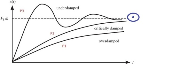
Suppose there are 3 persons P1, P2 and P3 as marked in the figure. All have to reach the center of the blue ring ( Steady State Value). Now to complete the errand all three get into 3 different airplanes : Over damped (O), Critically damped (C) and Under damped(U). Now I would like you to pay attention to both the time and displacement axis considering the displacement axis as the vertical distance of planes from ground.
Over Damped: The O airplane takes off very slowly and hence has a very high value of Rise Time as compared to other two systems. Rise time being defined as time taken to reach the level of center of the blue denoted by dotted line in the figure. Also due to some navigational anomalies it never reaches its destination and stays below the required height.
Critically Damped: The C plane is better than the O and almost (asymptotically) reaches the target and that too at a better speed and less time than O.
Under Damped: The U plane pilot is very enthusiastic and in its excitement goes at very high speed hence goes pass the target and that too in very less time (Rise Time) as compared to other two planes. Releasing his mistake it again comes back but again enthusiasm kicks in and he again passes the destination this time in opposite direction. This process continues until a specific time until he is settled. We call this time as the Settling Time and after this time he finally reaches his destination.
So in our little story the three paths takes by the planes represents the 3 time responses of Second order system when subjected to unit step response. Main difference lies in their Rise Time and Settling time and final steady state value achieved which dictate various design parameters in control systems.

 genius_generous answered 3 years ago
Related Solutions
A. What is an electrical transformer? Discuss basic principles of operation and applications of electrical transformers....
What are applications of the USA principles in converting a manual operation to automation?
Discuss the basic principles of cash management.
Discuss, briefly, the basic principles of the experimental design.
How to explain the basic principles, instrument operation and the application of Microwave Induced Plasma -...
Under basic electrical engineering, discuss and make summary on electrical lighting and heating requirements. The report...
Explain the basic operation of an operation amplifier. What are the most significant characteristics of such...
Explain 3 of the basic principles of lending. What are the consequences of violating these principles...
discuss the academic applications of memory models and try to apply the principles to yourself. Using...
What are the connections between accounting principles and their specific practical applications?
- Two 10-cm-diameter charged rings face each other, 15cm apart. The left ring is charged to -29nC...
- Under what conditions would it be possible for an excise tax to have no efficiency cost...
- explain the difference between activities and financial statements of service businesses and merchandising businesses.
- 2. Compare and compare the matrix multiplication algorithm and the Floyd-Warshall algorithm to find all pairs...
- Q: 50.00 ml of 0.5216 M copper(II) nitrate solution is combined with 100.0 ml of 0.5580...
- This is a business law question. Explain how environmental laws regulate the use of toxic substances...
- A sky diver and her parachute system weigh a total of 800 N. She is falling...