Question
In: Computer Science
1. The Context Diagram is one of the first diagrams to be generated in an SDLC....
1. The Context Diagram is one of the first diagrams to be
generated in an SDLC.
If the External Entities are not
correctly identified when developing the Context Diagram,
explain the effect on the Event
Table and the Use Case Diagram.
Explain also how the Context Diagram and
Event Table could be tested to ensure accuracy
2. Subject is System Analysis and Design
Solutions
Expert Solution
Answer:-
1)ans:-
The purpose of use case diagram is to capture the dynamic aspect of a system. However, this definition is too generic to describe the purpose, as other four diagrams (activity, sequence, collaboration, and Statechart) also have the same purpose. We will look into some specific purpose, which will distinguish it from other four diagrams.
Use case diagrams are used to gather the requirements of a system including internal and external influences. These requirements are mostly design requirements. Hence, when a system is analyzed to gather its functionalities, use cases are prepared and actors are identified.
When the initial task is complete, use case diagrams are modelled to present the outside view.
In brief, the purposes of use case diagrams can be said to be as follows −
-
Used to gather the requirements of a system.
-
Used to get an outside view of a system.
-
Identify the external and internal factors influencing the system.
-
Show the interaction among the requirements are actors.
How to Draw a Use Case Diagram?
Use case diagrams are considered for high level requirement analysis of a system. When the requirements of a system are analyzed, the functionalities are captured in use cases.
We can say that use cases are nothing but the system functionalities written in an organized manner. The second thing which is relevant to use cases are the actors. Actors can be defined as something that interacts with the system.
Actors can be a human user, some internal applications, or may be some external applications. When we are planning to draw a use case diagram, we should have the following items identified.
-
Functionalities to be represented as use case
-
Actors
-
Relationships among the use cases and actors.
Use case diagrams are drawn to capture the functional requirements of a system. After identifying the above items, we have to use the following guidelines to draw an efficient use case diagram
-
The name of a use case is very important. The name should be chosen in such a way so that it can identify the functionalities performed.
-
Give a suitable name for actors.
-
Show relationships and dependencies clearly in the diagram.
-
Do not try to include all types of relationships, as the main purpose of the diagram is to identify the requirements.
-
Use notes whenever required to clarify some important points.
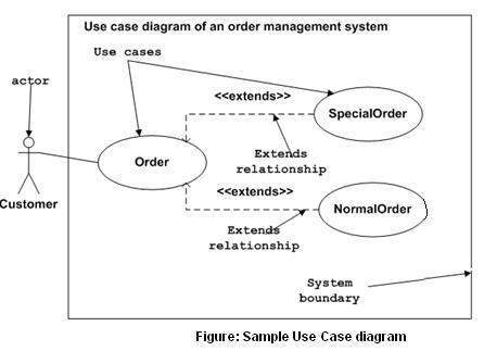
Following is a sample use case diagram representing the order management system. Hence, if we look into the diagram then we will find three use cases (Order, SpecialOrder, and NormalOrder) and one actor which is the customer.
The SpecialOrder and NormalOrder use cases are extended from Order use case. Hence, they have extended relationship. Another important point is to identify the system boundary, which is shown in the picture. The actor Customer lies outside the system as it is an external user of the system.
Where to Use a Use Case Diagram?
As we have already discussed there are five diagrams in UML to model the dynamic view of a system. Now each and every model has some specific purpose to use. Actually these specific purposes are different angles of a running system.
To understand the dynamics of a system, we need to use different types of diagrams. Use case diagram is one of them and its specific purpose is to gather system requirements and actors.
Use case diagrams specify the events of a system and their flows. But use case diagram never describes how they are implemented. Use case diagram can be imagined as a black box where only the input, output, and the function of the black box is known.
These diagrams are used at a very high level of design. This high level design is refined again and again to get a complete and practical picture of the system. A well-structured use case also describes the pre-condition, post condition, and exceptions. These extra elements are used to make test cases when performing the testing.
Although use case is not a good candidate for forward and reverse engineering, still they are used in a slightly different way to make forward and reverse engineering. The same is true for reverse engineering. Use case diagram is used differently to make it suitable for reverse engineering.
In forward engineering, use case diagrams are used to make test cases and in reverse engineering use cases are used to prepare the requirement details from the existing application.
2)ans:-
Systems development is systematic process which includes phases such as planning, analysis, design, deployment, and maintenance. Here, in this tutorial, we will primarily focus on −
- Systems analysis
- Systems design
Systems Analysis
It is a process of collecting and interpreting facts, identifying the problems, and decomposition of a system into its components.
System analysis is conducted for the purpose of studying a system or its parts in order to identify its objectives. It is a problem solving technique that improves the system and ensures that all the components of the system work efficiently to accomplish their purpose.
Analysis specifies what the system should do.
Systems Design
It is a process of planning a new business system or replacing an existing system by defining its components or modules to satisfy the specific requirements. Before planning, you need to understand the old system thoroughly and determine how computers can best be used in order to operate efficiently.
System Design focuses on how to accomplish the objective of the system.
System Analysis and Design (SAD) mainly focuses on −
- Systems
- Processes
- Technology
What is a System?
The word System is derived from Greek word Systema, which means an organized relationship between any set of components to achieve some common cause or objective.
A system is “an orderly grouping of interdependent components linked together according to a plan to achieve a specific goal.”
Constraints of a System
A system must have three basic constraints −
-
A system must have some structure and behavior which is designed to achieve a predefined objective.
-
Interconnectivity and interdependence must exist among the system components.
-
The objectives of the organization have a higher priority than the objectives of its subsystems.
For example, traffic management system, payroll system, automatic library system, human resources information system.
Properties of a System
A system has the following properties −
Organization
Organization implies structure and order. It is the arrangement of components that helps to achieve predetermined objectives.
Interaction
It is defined by the manner in which the components operate with each other.
For example, in an organization, purchasing department must interact with production department and payroll with personnel department.
Interdependence
Interdependence means how the components of a system depend on one another. For proper functioning, the components are coordinated and linked together according to a specified plan. The output of one subsystem is the required by other subsystem as input.
Integration
Integration is concerned with how a system components are connected together. It means that the parts of the system work together within the system even if each part performs a unique function.
Central Objective
The objective of system must be central. It may be real or stated. It is not uncommon for an organization to state an objective and operate to achieve another.
The users must know the main objective of a computer application early in the analysis for a successful design and conversion.
Elements of a System
The following diagram shows the elements of a system −

Outputs and Inputs
-
The main aim of a system is to produce an output which is useful for its user.
-
Inputs are the information that enters into the system for processing.
-
Output is the outcome of processing.
Processor(s)
-
The processor is the element of a system that involves the actual transformation of input into output.
-
It is the operational component of a system. Processors may modify the input either totally or partially, depending on the output specification.
-
As the output specifications change, so does the processing. In some cases, input is also modified to enable the processor for handling the transformation.
Control
-
The control element guides the system.
-
It is the decision–making subsystem that controls the pattern of activities governing input, processing, and output.
-
The behavior of a computer System is controlled by the Operating System and software. In order to keep system in balance, what and how much input is needed is determined by Output Specifications.
Feedback
-
Feedback provides the control in a dynamic system.
-
Positive feedback is routine in nature that encourages the performance of the system.
-
Negative feedback is informational in nature that provides the controller with information for action.
Environment
-
The environment is the “supersystem” within which an organization operates.
-
It is the source of external elements that strike on the system.
-
It determines how a system must function. For example, vendors and competitors of organization’s environment, may provide constraints that affect the actual performance of the business.
Boundaries and Interface
-
A system should be defined by its boundaries. Boundaries are the limits that identify its components, processes, and interrelationship when it interfaces with another system.
-
Each system has boundaries that determine its sphere of influence and control.
-
The knowledge of the boundaries of a given system is crucial in determining the nature of its interface with other systems for successful design.
Types of Systems
The systems can be divided into the following types −
Physical or Abstract Systems
-
Physical systems are tangible entities. We can touch and feel them.
-
Physical System may be static or dynamic in nature. For example, desks and chairs are the physical parts of computer center which are static. A programmed computer is a dynamic system in which programs, data, and applications can change according to the user's needs.
-
Abstract systems are non-physical entities or conceptual that may be formulas, representation or model of a real system.
Open or Closed Systems
-
An open system must interact with its environment. It receives inputs from and delivers outputs to the outside of the system. For example, an information system which must adapt to the changing environmental conditions.
-
A closed system does not interact with its environment. It is isolated from environmental influences. A completely closed system is rare in reality.
Adaptive and Non Adaptive System
-
Adaptive System responds to the change in the environment in a way to improve their performance and to survive. For example, human beings, animals.
-
Non Adaptive System is the system which does not respond to the environment. For example, machines.
Permanent or Temporary System
-
Permanent System persists for long time. For example, business policies.
-
Temporary System is made for specified time and after that they are demolished. For example, A DJ system is set up for a program and it is dissembled after the program.
Natural and Manufactured System
-
Natural systems are created by the nature. For example, Solar system, seasonal system.
-
Manufactured System is the man-made system. For example, Rockets, dams, trains.
Deterministic or Probabilistic System
-
Deterministic system operates in a predictable manner and the interaction between system components is known with certainty. For example, two molecules of hydrogen and one molecule of oxygen makes water.
-
Probabilistic System shows uncertain behavior. The exact output is not known. For example, Weather forecasting, mail delivery.
Social, Human-Machine, Machine System
-
Social System is made up of people. For example, social clubs, societies.
-
In Human-Machine System, both human and machines are involved to perform a particular task. For example, Computer programming.
-
Machine System is where human interference is neglected. All the tasks are performed by the machine. For example, an autonomous robot.
Man–Made Information Systems
-
It is an interconnected set of information resources to manage data for particular organization, under Direct Management Control (DMC).
-
This system includes hardware, software, communication, data, and application for producing information according to the need of an organization.
Man-made information systems are divided into three types −
-
Formal Information System − It is based on the flow of information in the form of memos, instructions, etc., from top level to lower levels of management.
-
Informal Information System − This is employee based system which solves the day to day work related problems.
-
Computer Based System − This system is directly dependent on the computer for managing business applications. For example, automatic library system, railway reservation system, banking system, etc.
Systems Models
Schematic Models
-
A schematic model is a 2-D chart that shows system elements and their linkages.
-
Different arrows are used to show information flow, material flow, and information feedback.
Flow System Models
-
A flow system model shows the orderly flow of the material, energy, and information that hold the system together.
-
Program Evaluation and Review Technique (PERT), for example, is used to abstract a real world system in model form.
Static System Models
-
They represent one pair of relationships such as activity–time or cost–quantity.
-
The Gantt chart, for example, gives a static picture of an activity-time relationship.
Dynamic System Models
-
Business organizations are dynamic systems. A dynamic model approximates the type of organization or application that analysts deal with.
-
It shows an ongoing, constantly changing status of the system. It consists of −
-
Inputs that enter the system
-
The processor through which transformation takes place
-
The program(s) required for processing
-
The output(s) that result from processing.
-
Categories of Information
There are three categories of information related to managerial levels and the decision managers make.
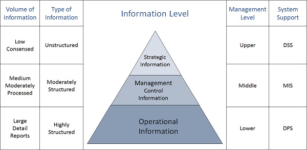
Strategic Information
-
This information is required by topmost management for long range planning policies for next few years. For example, trends in revenues, financial investment, and human resources, and population growth.
-
This type of information is achieved with the aid of Decision Support System (DSS).
Managerial Information
-
This type of Information is required by middle management for short and intermediate range planning which is in terms of months. For example, sales analysis, cash flow projection, and annual financial statements.
-
It is achieved with the aid of Management Information Systems (MIS).
Operational information
-
This type of information is required by low management for daily and short term planning to enforce day-to-day operational activities. For example, keeping employee attendance records, overdue purchase orders, and current stocks available.
-
It is achieved with the aid of Data Processing Systems (DPS).
 venereology answered 1 year ago
Related Solutions
Draw Data Flow Diagrams for the following system. Starting with a context diagram, draw as many...
1.For an information system at a library, draw i. a context diagram ii. a diagram O...
Systems Analysis and Design Create a Context Diagram for a purchasing system. Create this first level...
5. Describe the systems development life cycle (SDLC) methodology in the context of a “real” example....
QUESTION 1 One of the approach to SDLC is the adaptive approach. Within this approach,...
GUIDELINES: Context diagram should fit to one page. Use the mane of information system...
Draw a schematic diagram and a context diagram for a standard blender. Identify all of the...
Develop a Data Flow Diagram (DFD), Context Diagram and Level 1-2-3 for Cost Management System in...
Task # 1: Create a Context Diagram that describes the following: A library management system that...
Create one Main Use Case Diagram & five detailed use case diagrams for BigBasket platform. These...
- In 2012, cost per Medicare beneficiary did what?
- 3. A. What techniques can a firm use to optimize demand deposit holdings? B. How do...
- The half-life of mercury-197 is 64.1 hours. If a patient undergoing a kidney scan is given...
- Double bonds react with Br2 to form a dibromide. Isobutylene undergoes cationic polymerization under conditions where...
- 1. Which sex chromosomes are limited to only one sex? A. X and Z B. X...
- prepare a tecnical report that discuss about "A custom Union (CU) constitute a partial movement towards...
- in your own opinion, It has been said that a smartphone is a computer in your...